
Skip to content

What Are Bevel Gears and How Do They Work?

Bevel Gears are conical-toothed machine elements that transfer torque between intersecting shafts. Their teeth change rotational direction, often by 90 degrees. You can find them inside vehicle differentials, industrial reducers, robotics, and compact drive systems.

Gear specialist Dr. Hermann J. Stadtfeld has stated, “The gear is the heart of every gearbox.” This concise observation explains their importance. A bevel gear is not merely a wheel with angled teeth. Its pitch surface resembles a cone, while tooth geometry controls contact, noise, load capacity, and service life. Small design errors can create vibration. Heat can follow.

Imagine two shafts meeting like the hands of a mechanical elbow. One bevel gear drives the other across that angle. Straight bevel gears are simple and economical, but they can sound harsh at higher speeds. Spiral bevel gears engage more gradually, improving smoothness and load sharing. Hypoid gears offset the shafts and can deliver higher torque, although they demand careful lubrication and adjustment.

Reliable performance depends on more than selecting a gear type. Engineers consider module, pressure angle, ratio, speed, torque, material, tooth contact, and housing stiffness. Manufacturing accuracy matters. So does installation. Even a high-quality gear may fail when backlash or alignment is incorrect.

This guide examines what Bevel Gears are, how they work, and where their advantages become practical. It also acknowledges a common limitation: simplified diagrams can hide real contact patterns. Understanding that gap helps readers judge designs more realistically.
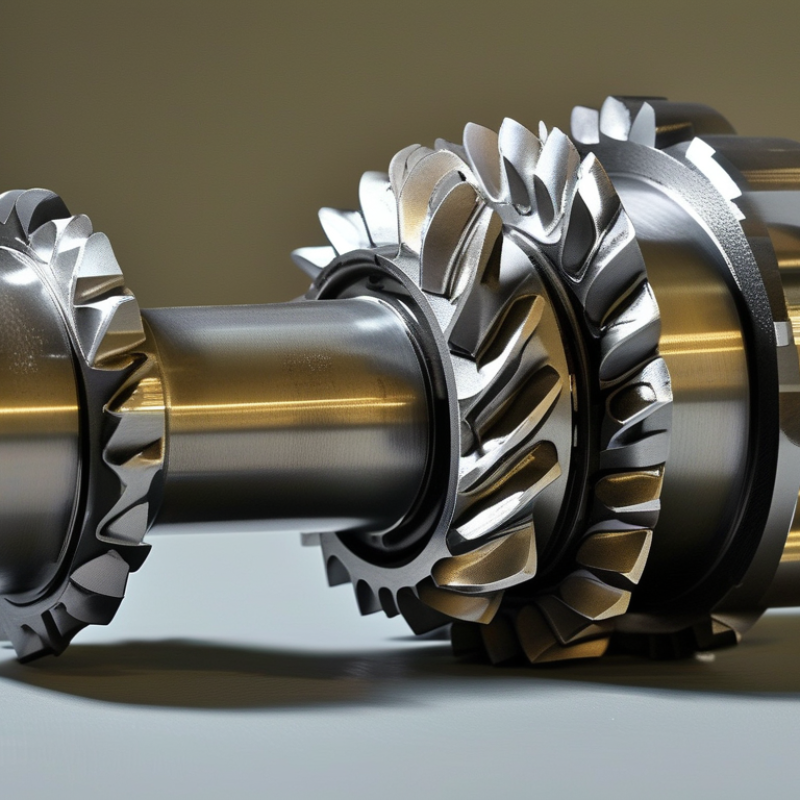
What Are Bevel Gears and How Do They Work?

What Are Bevel Gears and What Makes Them Different?

Bevel gears are toothed wheels that transfer power between intersecting shafts. Their teeth form on a cone-shaped surface. This shape sets them apart from ordinary spur gears, whose teeth sit on cylindrical surfaces. A bevel gear can change rotation direction, commonly by 90 degrees. That angle matters. The gear pair also changes torque and speed according to their tooth counts.

In a working gearbox, the driving gear pushes the mating gear across angled tooth surfaces. Straight bevel gears have direct, sharp tooth engagement and suit moderate speeds. Spiral bevel gears use curved teeth that contact more gradually. They usually operate more quietly and carry higher loads. However, their curved teeth can create axial thrust. Designers must check shaft support, bearing capacity, lubrication, and tooth contact. A small installation error can produce uneven wear.

Bevel gears also differ from worm gears and helical gears because their main purpose involves changing shaft direction through conical geometry. Their performance depends on more than the gear ratio. Backlash, mounting distance, surface finish, and operating temperature all influence reliability. During a practical inspection, technicians may find polishing on one tooth side or small pits near the heel. These marks can indicate misalignment or excessive load. This is where simple explanations fail. Even a well-designed gear set can run poorly when assembly tolerances are ignored. In my view, maintenance records should include contact patterns, not only noise readings. Noise can appear after damage has already started.

How Bevel Gears Transfer Motion Between Intersecting Shafts

What Are Bevel Gears and How Do They Work?

How Bevel Gears Transfer Motion Between Intersecting Shafts

Bevel gears transfer rotation between shafts that meet at an angle, often 90 degrees. Their teeth sit on cone-shaped surfaces, rather than flat cylinders. When the driving gear turns, its teeth push against the matching teeth of the second gear. This changes the direction of motion while transmitting torque.

The gear ratio depends on the tooth counts. A larger driven gear turns more slowly but produces greater torque. A smaller driven gear increases speed, with less torque available. Straight bevel teeth are simple and economical. Spiral bevel teeth engage more gradually, which can reduce noise and vibration during operation.

Accurate alignment matters. The shaft intersection, mounting distance, tooth contact, and lubrication must match the design. Even a small positioning error can concentrate force along one tooth edge. The result may be uneven wear, heat, or a sharp whining sound. The ideal geometry is tidy. Real assemblies are not.

During inspection, technicians often rotate the gears by hand before applying a load. They look for tight spots, backlash, and contact marks across the tooth faces. Backlash is necessary, but excessive clearance can cause impact loading. Too little clearance may cause binding as temperatures rise. In practice, installation tolerances and housing stiffness can matter as much as the gear profile itself.

Key Components and Geometric Features of a Bevel Gear Set

A bevel gear set changes torque direction, usually through intersecting shafts at 90 degrees. Its key parts are the pinion, gear wheel, teeth, cone surfaces, and shaft bores. The pinion drives the larger gear, while the tooth geometry controls contact, speed, and load transfer. In practice, even a small mounting error can create uneven contact marks.

The pitch cone is the central geometric reference. Its apex should meet the shaft intersection point. The pitch angle divides the cone between the two gears, while the pressure angle shapes how force travels across each tooth. Spiral bevel gears add curved teeth, which usually provide smoother engagement than straight teeth. However, they can generate axial thrust and demand more careful bearing support. AGMA 2005-D03 and ISO 23509 define important bevel gear geometry and terminology used in engineering design.

Efficiency matters because gears transmit energy repeatedly under load. The U.S. Department of Energy’s Industrial Motor Systems Market Assessment estimated that motor systems used about 68% of U.S. manufacturing electricity. That figure shows why small transmission losses deserve attention. Good alignment, correct backlash, suitable lubrication, and controlled tooth contact reduce wasted power. Real installations are less perfect than drawings suggest. Thermal expansion, housing distortion, and assembly variation can shift the contact pattern. Engineers should inspect the teeth after testing, not trust calculations alone.

Common Types of Bevel Gears and Their Operating Principles

What Are Bevel Gears and How Do They Work?

Bevel gears transmit motion between intersecting shafts, usually at a 90-degree angle. Their conical teeth change both rotation direction and speed. When the input gear turns, its teeth push against the mating gear’s sloped teeth. The output shaft then rotates around a different axis. Gear size controls the speed ratio and available torque.

Straight bevel gears have teeth cut directly across the cone. They are simple, economical, and suitable for moderate speeds. However, tooth contact begins suddenly, which can create noise and vibration. Spiral bevel gears use curved teeth that engage gradually. This produces smoother running and higher load capacity, but it also creates axial thrust. Bearings must handle it.

Zerol bevel gears use curved teeth with nearly zero spiral angle. They offer quieter operation than straight gears, with less axial force than spiral designs. Miter gears are matching bevel gears with a 1:1 ratio. They change shaft direction without changing speed. Hypoid gears place the shafts on offset centerlines, allowing compact layouts and strong torque transfer. Their sliding action demands careful lubrication and accurate alignment. This distinction is easy to blur. Real machines are less tidy. Tooth contact depends on housing stiffness, backlash, surface finish, and manufacturing accuracy. A gear may look correct yet run poorly if its mounting distance is wrong. Experienced technicians often inspect contact patterns, temperature, and operating sound instead of trusting dimensions alone.

What Are Bevel Gears and How Do They Work?

Bevel gears transmit rotary motion between intersecting or offset shafts by using conical gear surfaces. The output speed is determined by the tooth-count ratio: Output Speed = Input Speed × Driver Teeth ÷ Driven Teeth.

Common Types of Bevel Gears and Their Operating Principles

The chart uses representative tooth-count configurations at an input speed of 1,000 revolutions per minute. These calculations illustrate how different bevel gear arrangements can change output speed; tooth counts vary by application.

Straight bevel gears use straight teeth and are relatively simple to manufacture. Spiral bevel gears have curved teeth that engage more gradually, generally producing smoother and quieter operation. Zerol bevel gears have curved teeth with a nominal spiral angle near zero, combining features of straight and spiral designs. Hypoid gears resemble spiral bevel gears but use offset, non-intersecting shaft axes, allowing compact layouts and higher reduction ratios.

Applications, Advantages, and Limitations of Bevel Gears

What Are Bevel Gears and How Do They Work?

Bevel gears transfer motion between intersecting shafts, usually at a 90-degree angle. Their cone-shaped teeth change rotational direction while transmitting torque. Straight, spiral, and hypoid forms suit different operating conditions. In machinery, they appear in vehicle differentials, right-angle drives, printing equipment, and compact industrial tools. Their geometry helps engineers fit power transmission into tight spaces.

A major advantage is directional flexibility. Bevel gears can provide reliable speed reduction and maintain controlled movement in compact assemblies. Spiral teeth usually run more quietly than straight teeth, especially under steady loads. However, performance depends heavily on accurate alignment, tooth contact, lubrication, and housing stiffness. Poor setup can create vibration, heat, and rapid wear. They may also cost more to manufacture than simpler gear arrangements. A design can look efficient on paper, yet fail when installation tolerances are ignored. That limitation deserves attention.

Tips: Match the gear type to speed, torque, noise, and shock requirements. Check shaft angles before selecting tooth geometry. Use the manufacturer’s recommended lubricant and inspect contact patterns during maintenance. Watch for pitting, unusual noise, or rising temperature. Small errors matter. Also, do not assume a bevel gear is automatically the best right-angle solution; a simpler mechanism may be more practical after real space, load, and service conditions are measured.

What Are Bevel Gears and How Do They Work? — Applications, Advantages, and Limitations

Dimension Description Typical Applications Key Advantages or Limitations
Definition Bevel gears are toothed gears with conical pitch surfaces. They transmit rotary motion and torque between intersecting shafts, commonly at a 90-degree angle. Right-angle drives, compact power-transmission systems, machine tools, and vehicle drivetrains. They change both the direction of rotation and the direction of power transmission within a relatively compact assembly.
Operating Principle When the driving gear rotates, its teeth mesh with the teeth of the mating gear. The contact transfers torque while the conical geometry redirects the motion between the shafts. Applications requiring an angular connection between an input shaft and an output shaft. Correct tooth engagement, shaft alignment, lubrication, and mounting accuracy are essential for reliable operation.
Common Gear Types
  • Straight bevel: straight teeth and relatively simple construction.
  • Spiral bevel: curved teeth for smoother and quieter engagement.
  • Zero bevel: curved teeth with approximately zero spiral angle.
  • Miter gear: usually a matched pair with equal tooth counts and a 1:1 ratio.
Simple mechanisms, quiet power transmission, precision equipment, and right-angle motion transfer. Spiral forms generally provide smoother operation but are more complex to manufacture and may produce greater axial thrust.
Shaft Arrangement The shafts normally intersect, although specialized bevel-gear arrangements can accommodate different geometric layouts. Right-angle gearboxes, steering systems, conveyor drives, and industrial machinery. They are suitable when shafts must meet at an angle, but they are not the default choice for parallel-shaft transmission.
Speed and Torque Ratio The speed ratio is determined by the relationship between the tooth counts of the mating gears. A larger driven gear reduces speed and increases torque, while a smaller driven gear has the opposite effect. Speed reduction, torque multiplication, directional drives, and motion synchronization. Gear ratio flexibility is useful, but higher ratios may require additional stages, increased size, or higher tooth loads.
Automotive Applications Bevel gears can redirect torque from a driveshaft to an axle or differential assembly and can support power transfer between intersecting shafts. Differentials, axle assemblies, transfer mechanisms, and selected four-wheel-drive systems. They enable compact driveline layouts, but noise, heat, tooth loading, and lubrication must be carefully controlled.
Industrial Applications They provide angular power transmission in equipment where the motor and driven component cannot share the same shaft axis. Machine tools, packaging equipment, printing machinery, conveyors, pumps, mixers, and material-handling systems. They offer layout flexibility and dependable torque transmission when properly selected and aligned.
Aerospace and Marine Uses Precision bevel gears can transfer motion in systems with strict requirements for mass, space, reliability, and directional changes. Actuation systems, auxiliary drives, marine propulsion arrangements, and compact control mechanisms. High performance is possible, but manufacturing quality, inspection, weight control, and maintenance requirements are demanding.
Main Advantages
  • Changes the direction of power transmission.
  • Works well in compact right-angle arrangements.
  • Can provide useful speed and torque ratios.
  • Spiral designs can operate more smoothly than straight-tooth designs.
  • Available in a broad range of sizes and configurations.
Compact machinery, angular drives, synchronized mechanisms, and applications requiring controlled speed reduction. Good design flexibility and efficient torque transfer when the gear pair is correctly sized and installed.
Main Limitations
  • More sensitive to alignment errors than many simpler gear arrangements.
  • Can generate axial and radial forces, especially in spiral designs.
  • May require specialized manufacturing and inspection.
  • Usually needs appropriate lubrication and housing support.
  • Tooth noise and vibration can increase under overload or poor setup.
High-load, high-speed, or space-limited systems that require careful engineering. Initial cost, maintenance needs, and installation precision may be higher than for simpler gear types.
Efficiency Factors Efficiency depends on tooth geometry, surface finish, lubrication, speed, load, bearing condition, and alignment. Continuous-duty gearboxes, automotive systems, and industrial drives. Well-designed systems can be highly efficient, while friction, sliding, poor lubrication, and misalignment increase power loss.
Material and Manufacturing Considerations Gear materials are selected according to load, speed, wear resistance, shock loading, operating temperature, and environmental conditions. Common choices include alloy steels, stainless steels, cast irons, bronze-based materials, and engineering plastics. Industrial drives, food-processing equipment, precision instruments, and harsh or corrosive environments. Material selection affects strength, noise, durability, corrosion resistance, weight, and manufacturing cost.
Maintenance Requirements Routine care may include lubricant inspection or replacement, checking backlash, monitoring noise and vibration, examining tooth wear, and verifying shaft alignment. Gearboxes and machines operating continuously, under shock loads, or in dusty, wet, or high-temperature conditions. Regular maintenance helps prevent overheating, pitting, tooth breakage, excessive wear, and unplanned downtime.
Selection Criteria Important factors include transmitted power, input and output speed, required ratio, shaft angle, torque, duty cycle, space, noise limits, service conditions, lubrication, and expected service life. New equipment design, replacement gear selection, gearbox upgrades, and custom motion systems. Choosing the gear type solely by size or ratio can lead to premature failure; the complete operating environment must be evaluated.

Note: Actual performance depends on gear geometry, materials, manufacturing accuracy, load conditions, lubrication, installation quality, and operating environment.